Before being supplanted by the codex, scrolls were the primary medium for recording information. The scroll format imposed certain limitations on both reading and writing. Chief among these were the lack of random access and the underutilisation of the reverse side of the roll. The codex resolved both issues by enabling non-linear access through pagination and allowing mark-making on both sides of the page, effectively doubling the available surface for inscription.
With the advent of 3D printing (particularly in the context of the volumetric press), 3D printed books reintroduce the problem of single-sided mark-making. FFF 3D printing follows an additive model, in which objects are built layer by layer. When producing substrates within this model, the XY-plane is often utilised to fabricate the substrate. Printing the substrate flat on the print bed follows an intuitive logic similar to traditional papermaking, where pulp is spread thinly across a flat mesh and then dried. With this method, printing double-sided pages becomes challenging, as the verso (reverse side) is effectively “bound” to the print bed as the initial layer of deposition. This makes it difficult to print any marks on the verso without either introducing intermediate interface layers or embedding those marks directly within the first printed layer.
In FFF 3D printing, marks are deposited as layers that are materially continuous with the substrate itself. Unlike ink on paper, these 3D printed marks on the 3D printed substrate’s recto (front side) surface are neither technically nor materially distinct from the page, differing only in their conceptual designation as ‘marks’ and ‘substrate’. Utilising the XY-plane for the production of substrates necessitates the use of the Z-axis for printing of marks. This means that the fidelity of marks made on the surface of the ‘substrate layer(s)’ is directly affected by the deposition resolution of the printer. Printing fine details in TPU is also challenging with retractions turned on. This often presents challenges for printing small marks (small letters or punctuations in texts) for which purpose-built typefaces with specific design considerations, such as path traps, have to be devised.
However, FFF 3D printing offers an alternative approach that departs from the conventional XY-plane model of substrate production. As the technology advances (particularly in reducing kinematic noise caused by hardware vibration), it becomes feasible to print flexible materials, such as TPU, in an ‘upright’ orientation along the Z-axis. In this configuration, the page no longer needs to be laid flat on the print bed; instead, it is printed on its edge.
Fig. 1 Timelapse of two pieces of Manual (2026), 26 pages each, printed over approximately 90 hours in a single print.
The 3D printed book can be printed spine-first on the print bed (Fig. 1). This method relies on the XY-axes to generate marks. The toolhead extrudes continuous lines—straight paths establish the base structure of the substrate, while slight deviations in other paths induce reliefs on the surface, relative to the substrate. Repeated across successive layers, these minute variations and protusions accumulate into legible surface features and manifest as marks (Fig. 2). The substrate is being printed at the same time as the marks, more specifically, with the same toolpaths. This contrasts with the conventional XY-plane model of substrate production, where the marks are printed on a separate layer along the Z-axis. The conventional XY-substrate and Z-marks already collapse the distinction between ‘marks’ and ‘substrates’ into a single axis (Z). The XY-for-Z printing method further destabilises the distinction between the ‘mark’ and ‘substrate’, as the difference is no longer grounded in a discrete separation in the Z-axis, but instead arises from positional variation within a continuous and undifferentiated XY-plane (Fig. 4).
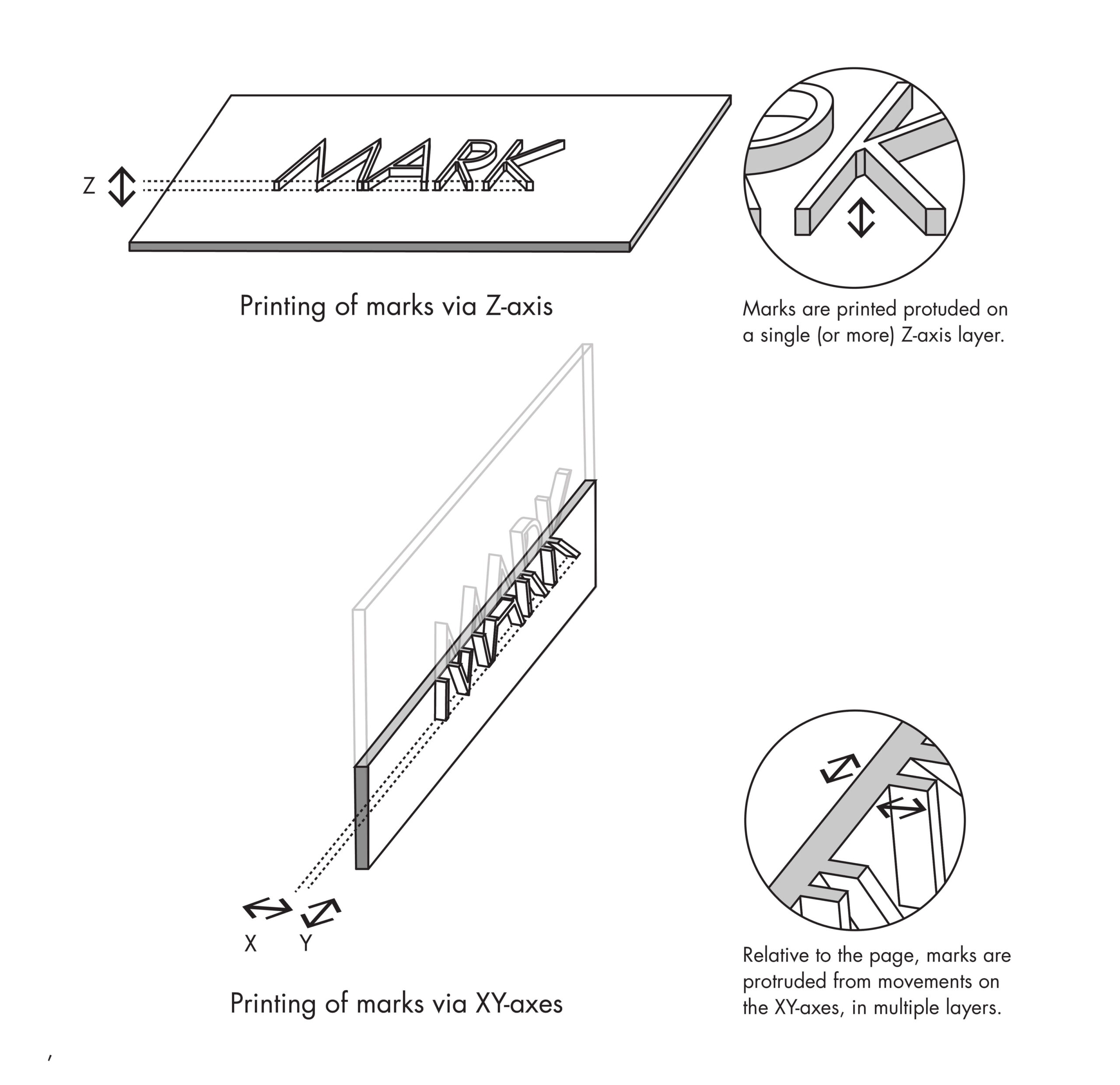
Fig. 2. Diagram showing the XY-for-Z mechanics.
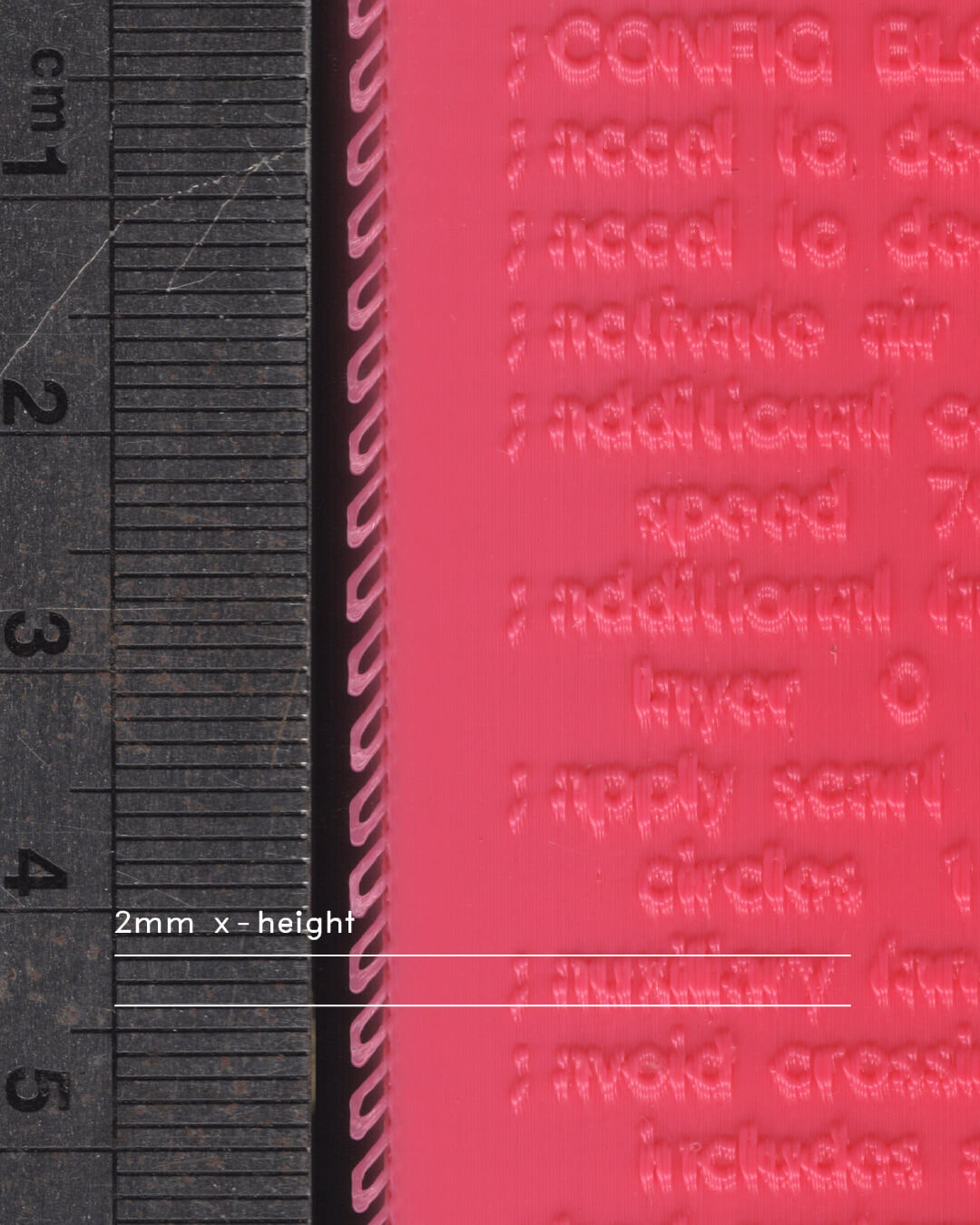
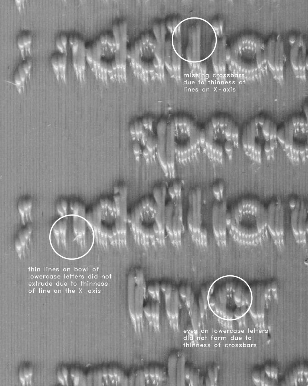
Fig. 3. Limitations of the XY-for-Z method for reproducing thinner details on the X-axis.
Essentially, the XY-for-Z method swaps the role of the production of marks and substrates between the XY- and Z-axes. It reintroduces double-sided printing to the volumetric press while significantly improving the fidelity of small text (2mm x-height) on the 3D printed page (Fig. 3). As the marks are interpreted by the slicer software as outer walls (Fig. 4), it is recommended to set the outer wall printing speed to below 30mm/s with retractions when printing with TPU of shore hardness between 90A and 95A, (with 90A yielding better results due to less warpage) and a raft. Direct feeding of the TPU filament is also recommended for optimal results.
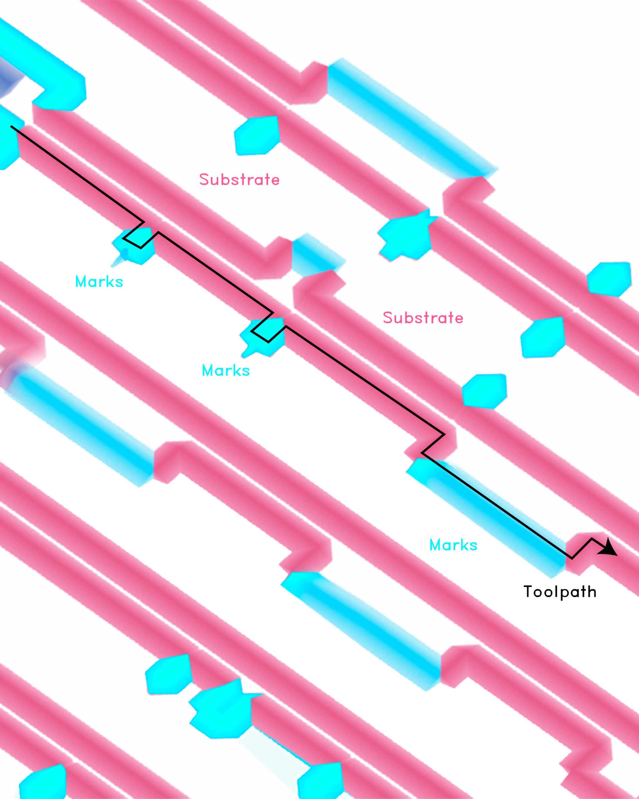
Fig. 4. Toolpaths for the XY-for-Z method to protrude marks.
While this method offers higher fidelity (Fig. 5) than XY-plane substrate production with Z-axis marks, it struggles with printing marks in materials distinct from the substrate. As the substrate is produced along the Z-axis at the same time as the marks on the XY-plane, the printer must extrude material as continuously as possible; any interruption or fluctuation in flow rate and pressure compromises extrusion reliability. This means that current multi-material technologies in FFF 3D printing, which rely on pausing and continuing prints, will not be ideal for this use case of extruding only small amounts of material in short bursts. As such, it is currently unfeasible to reliably print multi-material (or multi-colour) marks that differ from the substrate using this method, especially with flexible materials like TPU that require steady flow pressures for reliability.
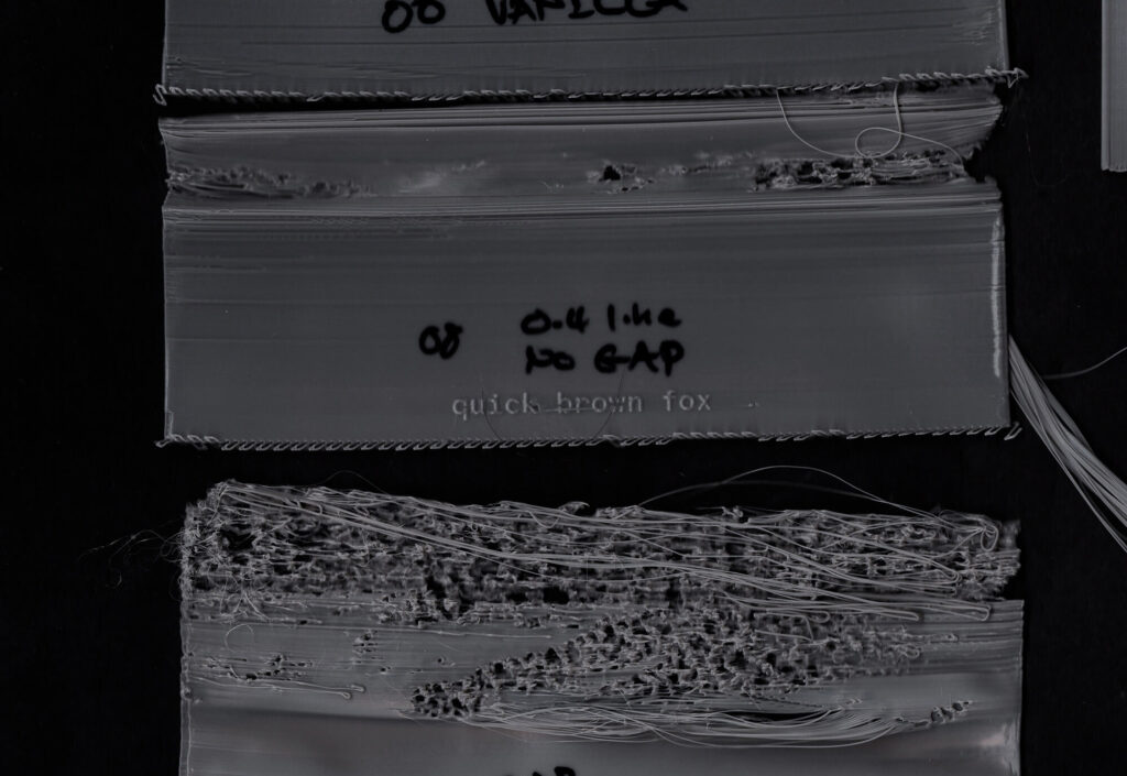
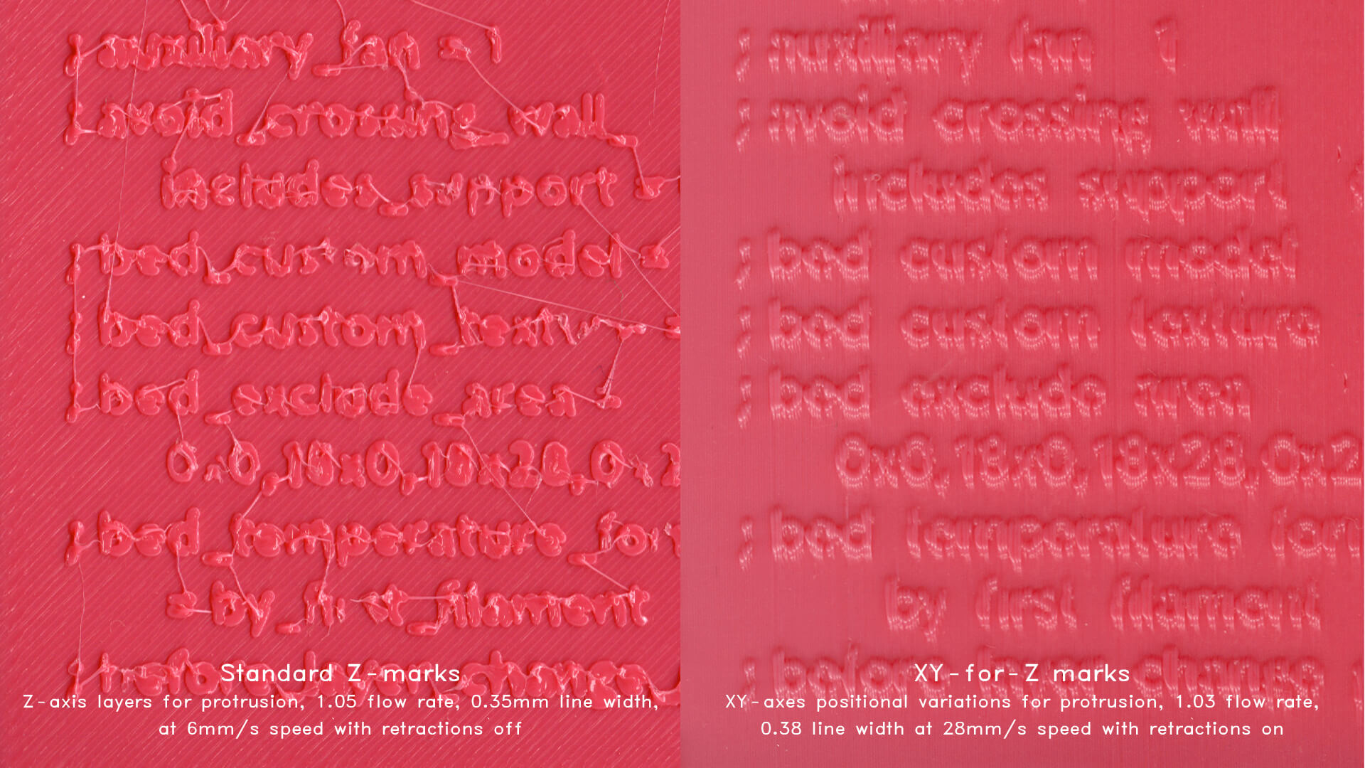
Fig. 5. Comparison between Standard Z-marks (non-path trapped) and XY-for-Z marks printed with 90A TPU.
Warping is an expected outcome when printing with XY-for-Z, as the resulting object consists of clusters of tall and thinly printed flexible walls. Thermal gradients resulting from the reheating of preceding layers can cause the printed layers to contract and curl upon cooling. With thin, flexible walls, this effect is exacerbated, causing the pages to warp in the YZ-axis. Warping can be reduced through a technique devised by hyperpress as deckle-edge supports (Fig. 6).
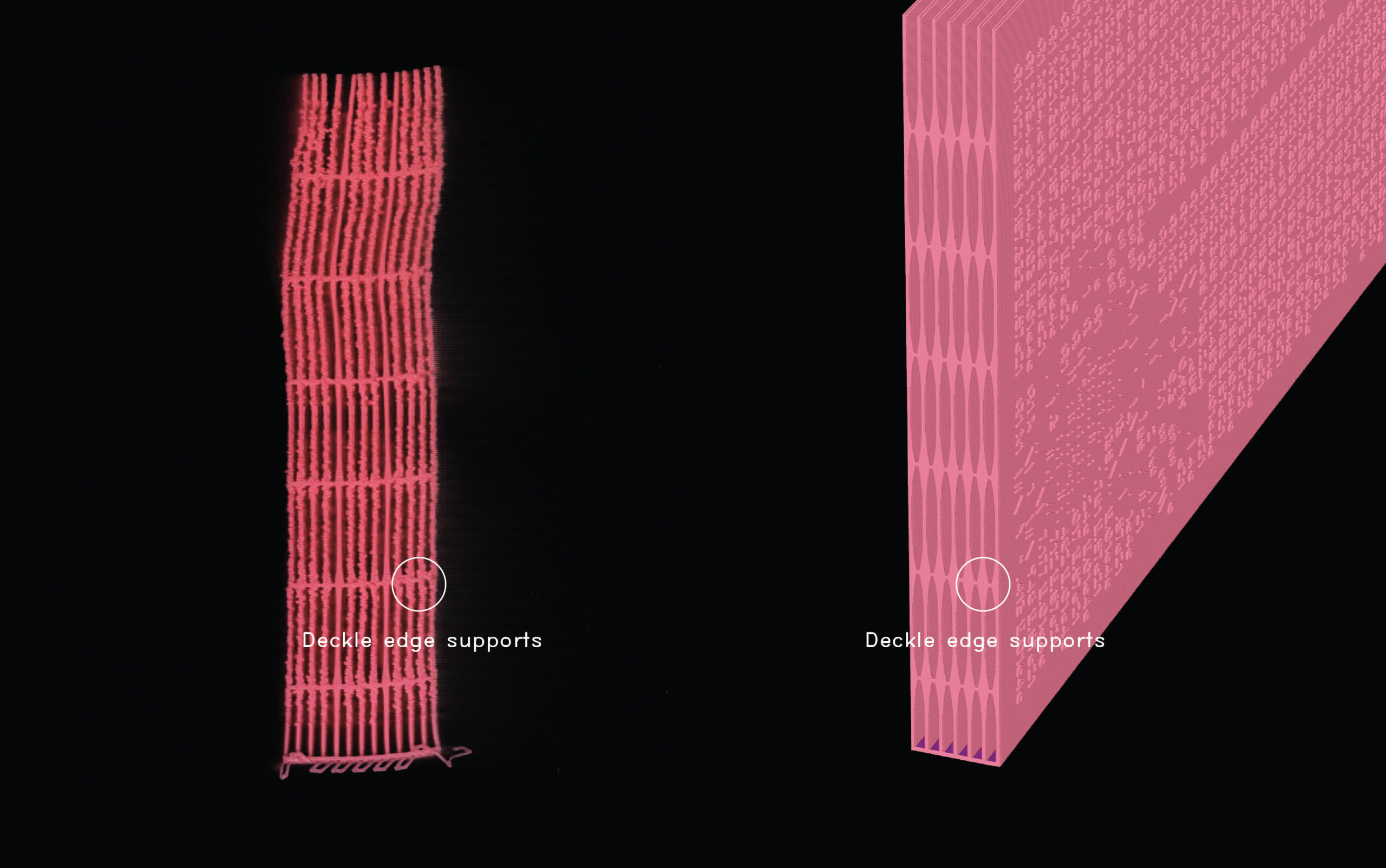
Fig. 6. An example of deckle edge supports (diamond shaped).
Deckle-edge supports are thin support structures designed to increase print reliability in the XY-for-Z method—manufacturing deckle edges in 3D printed pages in the process. By linking adjacent pages, these supports create a monobloc bracing system that stabilises the flexible structure during printing. Though not fully eliminating the warp, these supports are observed to help strengthen the structure at least in the lower to mid layers. These links should be designed in a way that connects pages with as little surface area as possible (for easy prying after print), while providing enough material to hold the pages together during print. These supports are also suitable spots to position the printing seams, as the edges are already rough.
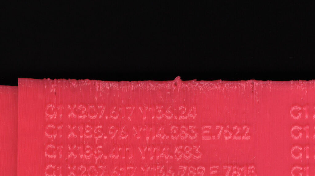
Fig. 7. Rough edges as an artefact of seam placement and deckle-edge supports of the XY-for-Z method.
Fig. 8. The prying process of the deckle-edge support. Deckle-edge supports should be designed to be easy to pry open pages.
These supports draw on the traditional deckle edge found in early paper books, where page edges were rough and feathered—an artefact of manual papermaking, the use of the wooden deckle, and the fibrous nature of the material. An XY-for-Z printed book with deckle-edge supports produces rough edges that recall these pre-mechanised artefacts (Fig. 7). Like its papermaking predecessor, this roughness arises from FFF deposition mechanics, seams, and the layer-based discretisation of slicer software. Before mechanised production, paper pages were often left untrimmed, requiring readers to “slice” them open, a process that produced similarly rough edges. The XY-for-Z 3D printed book likewise requires pages to be pried open, further contributing to the roughness (Fig. 8). Interestingly, ‘slicing’ returns not just as a post-production step but also as a pre-production process in 3D printing, operating in another register.
Fig. 9. Tomographic view of an XY-for-Z printed book.